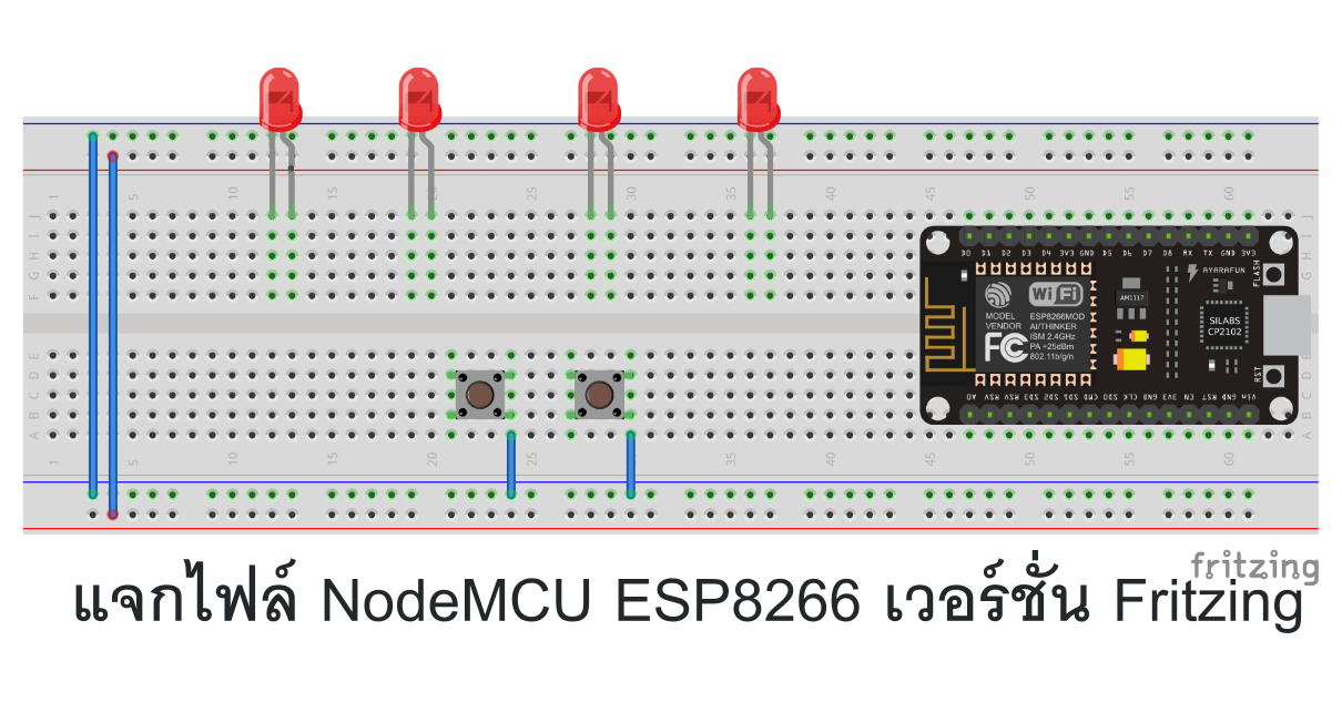

I see no reason we can't have our cake and eat it too. It seems that development has stalled for some time now, and it'd be a huge waste of Fritzing's potential if its development would get discontinued. But thanks so much for It would be amazing if there'd be a 3D view for Fritzing! I guess much more people would (be able to) contribute parts, causing more people to use Fritzing, stimulating further development.

The TO-220 looks exactly like I had in mind, but could it be that the dimensions are off? It's a little wider than real life and the tilted versions it seems. But just squares would already do for a start! The heatsinks i'm using now are 29*15mm and 30*10mm square, and 47*17 and 15*11mm and in H shape. And it doesn't help that if you place something in breadbord view, it's location in PCB view(or other views) doesn't match even close. I tried the PCB view, but the visual representation of breadbord view gives me a much better insight how to put things. In or mm is a better option (px can cause scaling Yes I suppose that's the view meant for that purpose, but I like the breadboard view so much. In or mm is a better option (px can cause scaling problems!) 'sparkfun-electromechanical-trimpot-trimpot_pth_s3_lock.fzp' 'sparkfun-electromechanical_trimpot-1_schematic.svg' If you wanted a smd part remove the copper0 definition from line 36 This is a through hole part as both copper0 and copper1 views are present. Looks good, the only thing the script found to bitch about (other than reference files which are essentially meaningless ) is the view box is in px:


 0 kommentar(er)
